The Deep Array Wake Model (DAWM) within Openwind is a modification which can be applied to any other wake model. Openwind contains a number of DAWM:
•Deep Array Eddy-Viscosity Wake Model (DAWM Eddy-Viscosity) - this is a combination of the standard Eddy-Viscosity model with a boundary layer wake model developed by UL based on a theory by Frandsen. More information is available in the DAWM white paper
•Deep Array Eddy-Viscosity Wake Model (DAWM Park Variant) - this is a combination of the standard Park model with the DAWM.
The default configuration of this modification involves the modelling of each individual turbine as a roughness element the width of the turbine rotor. In fact, the two IBLs resulting from such a distinct patch of roughness are initialized in place at the upper and lower edges of the rotor plane and extending in a square of side one rotor diameter centred on the turbine hub. This IBL pair is then allowed to propagate downwind, affecting the wind speed at each downwind turbine. This effect is modelled separately from standard wake models such as Park or the Eddy-Viscosity model and is combined by taking the maximum of the roughness effect and the standard wake effect.
The DAWM Eddy-Viscosity model is the UL default model for all energy assessments regardless of how many turbines are being modelled. The deep array effect emerges gradually and naturally as more rows of turbines are added.
The DAWM EV model has been tuned to data from Horns Rev and Nysted for offshore operation and to data from three separate sites in the Midwestern US for use inland.
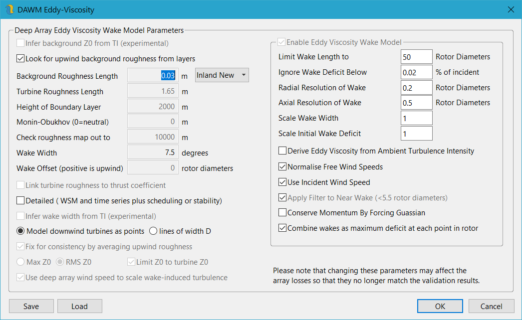
For this purpose, a drop-down option has been provided to enable easy setup for either inland or offshore wind farms (see figure 134). Users can configure drop-downs as "Offshore" or "Inland"—either as presets or "Custom"—to allow direct editing of the turbine and background roughness values.
For a fuller description of the theoretical basis and validation of this model, please see our white paper.
The values in the lower part of each DAWM dialog (DAWM Park, DAWM Eddy-Viscosity) correspond to the variables in the standard version of each of these wake models. As with the standard wake models, users modify the default values at their own risk.
The DAWM values in each case can be modified via the following fields:
•Infer background Z0 from TI (experimental) – this option is a potential replacement for using roughness maps to set the background shear profile against which the IBLs generated by the turbine rotors are contrasted. This is potentially a much faster way to run the DAWMEV and also has the added bonus of allowing the deep array effect to change with ambient turbulence.
•Look for upwind background roughness from layers - this option allows for repeatable estimates of background roughness length as well as allowing the background roughness to vary by direction. It is recommended to use the same kind of roughness raster that might be prepared for creating a wind flow. The roughness rasters should extend outwards from the turbines for at least 10km in every direction as outside of the roughness raster the background roughness defaults back to the value input in the dialog above. Clearly this method does require some processing and so for sites in which the background roughness is very uniform it can be better to uncheck this option and set an overall background roughness instead.
•Background Roughness Length - This value should reflect the general background roughness of the site if you are not using the option above to look for roughness from rasters.
•Turbine Roughness Length - This is the value of roughness which would result in the shear coefficient represented by the IBL initiated at the turbine.
•Height of Boundary Layer - This is the height above ground level to which hub height wind speeds are sheared up using the default background roughness before being sheared back down to hub height using the turbine-modified shear profile.
•Turbine Radius Multiplier - This scaling factor is applied to the effective width of each turbine rotor relative to its actual diameter (default = 1).
•Monin-Obukhov (Stability Length) - This parameter is used in the calculation of the shear ratio. At present, it is set to zero = neutral and should not be altered. A future version will include an improved representation of stability.
•Check roughness map out to – this is used with the option to look upwind for background roughness from layers. This is the maximum distance to look upwind for background roughness, so you should generally have a roughness map that extends at least this distance out from the turbine locations in every direction.
•Wake Width - this is the rate at which the wake expands behind the rotor. Larger values are indicated in the literature. However, these larger values do not give as good a match with empirical data.
•Link Turbine Roughness to Thrust Coefficient – this is experimental just now. It uses the value in the turbine roughness input box to scale a function of the turbine thrust coefficient. If adopted, this would mean that turbine roughness would be driven by the thrust coefficient and turbines with lower thrust curves would produce less deep wake effects.
•Infer wake width from TI (experimental) – allows the wake width to vary with the ambient TI. Higher TI will translate to wider wakes. The sin of the half-width of the wake grows at a rate equal to the ambient TI so a TI of 6% will translate to a wake-width of just over 6.8 degrees whereas an ambient TI of 10% will translate into a wake width of 11.5 degrees.
•Fix for consistency by averaging upwind roughness – this option will modify the model slightly so that global background roughness values have the same effect as uniform roughness maps. Checking this option means that the turbine roughness values needs to be changed to give the same validated results. Try changing the drop-down pre-set to find the suggested turbine roughness.
•Detailed - this is the most correct use of the model. However, it can result in very long processing times and is only really necessary when turbines are switching on and off at different wind speeds or times (see Turbine Scheduling ). In general, it is usually OK to leave this option off, especially when not calculating final energy numbers.
•RMS Z0/Max Z0 - This switch determines whether the roughness effect felt by each downwind turbine is calculated using the root-mean-square of the upwind roughness values in this sector (recommended) or the maximum upwind roughness effect (physically questionable - this option is scheduled for removal).
•Limit Z0 to turbine roughness length - when using the RMS Z0 combination option above, it is possible in very large wind farms to get roughness values exceeding the turbine roughness. This is unintended and so an option to limit the maximum roughness has been added.
The other options listed in figure 134 are explained in the section on the Eddy-Viscosity model.