Gridded-Turbine-Layer
This layer type fills a polygon or number of polygons with turbines. When selecting or editing a gridded turbine layout, the toolbar additions shown in figure 87 become active.

Figure 87: Gridded Layout Toolbar Options
The drop-list on the left gives the choice of squares or triangles as a starting point for the tiling. When working with circular offsets, the Bearing slider determines the orientation of individual rows of turbines whereas the Obliquity slider determines the angle at which turbines in one row are offset from the next. When working with elliptical offsets, the bearing becomes relative to the major angle of the ellipses and the obliquity tends to determine merely how closely packed the turbines are. Essentially these sliders are intended to provide a creative interface to the problem of designing a gridded layout in which the user can play with the sliders until the desired packing or total number of turbines is reached.
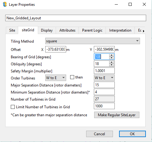
Figure 88: Gridded Site Orientation and Spacing
The deterministic part of the process is envisaged as being the minimum separation distance. Once this has been determined, the gridding algorithm takes care of maintaining the minimum separation distances and the user is free to design the gridded layout to their liking.
Figure 88 shows the settings that are specific to the gridded layout.
Tiling Method - this can be squares or triangles but in fact only squares should be used at present. An obliquity of +30 or -30 achieves the same result as switch to triangles.
Offset - this is a rather abstract concept used to adjust the tiling when it fails to fill the polygon. This is more naturally set by switch to edit mode and then dragging the turbines into the area of the polygon which the gridding algorithm is failing to fill.
Angle of grid - this is the angle set by the first slider in the toolbar
Obliquity - this is the angle set by the second slider
Safety Margin - this is the amount by which we want to multiply the minimum separation distance. The minimum value is 1.0
Order Turbines - this allows the user to determine how the turbines are numbered. It is not possible to label turbines in a gridded array. However, it is possible to choose to number the turbines in two different directions. The layout in figure 88 has been ordered from North to South then from West to East
Major Separation Distance – this is the distance that the turbines are separated in the major axis direction if this layer is using elliptical separation distances (otherwise “N/A”). It has to be at least the distance specified in the Site tab but can be more. This is the separation distance that the optimiser modifies.
Minimum Separation Distance – this is the distance that the turbines are separated in the minor axis direction if this layer is using elliptical separation distances (otherwise it is just the minimum separation distance). It has to be at least the distance specified in the Site tab but can be more. This is the separation distance that the optimiser modifies.
Number of Turbines in Grid – this is can convey information, but can also be set by the user and can be used by the optimiser.
Limit Number of Turbines in Grid – this is generally used in conjunction with the layout optimiser to fix a number of turbines. If it is used in conjunction with the optimiser for cost of energy, there is quite often a trade-off then between cable cost (driven by separation distance) and wake effects.
Make Site Layer - of course it is possible to label turbines and to move them individually by converting the gridded site layer into a regular site layer.
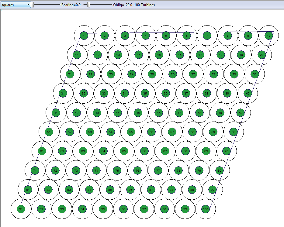
Figure 89: Example of a Gridded Site Layer Numbered NtoS then WtoE