Environmental-Sensor-Layer
EnvironmentalSensorLayers help users assess and limit environmental impact at points of interest. Generally, such layers can be digitized in Openwind or converted from a PointLayer such as a buildings layer.
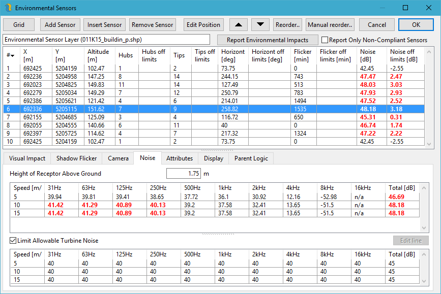
Figure 3: Environmental Sensor Layer Properties
Openwind offers a tab for each type of environmental impact it attempts to model: visual, noise and shadow flicker. The impacts shown in the Environmental-Sensor-Layer properties are recalculated each time the dialog is shown. You can output a report of all the environmental impacts using the Report Environmental Impacts button shown in figure 3. Checking the box next to that option will only output results for sensors which are non-compliant in some way. This means that a limit has been set for some type of impact and that limit has been broken (e.g. noise limit of 45 dB and noise level of 45.1 dB).
The Visual Impact tab in figure 4 outlines the visual impact at the currently selected point object in terms of the number of turbine hubs and tips visible (see Section 42 for more) as well as the horizontal or panoramic impact of each wind-farm (represented by different SiteLayers).
The Visual Impact tab allows the user to set limits on the visual impact at each location in the EnvironmentalSensorLayer.
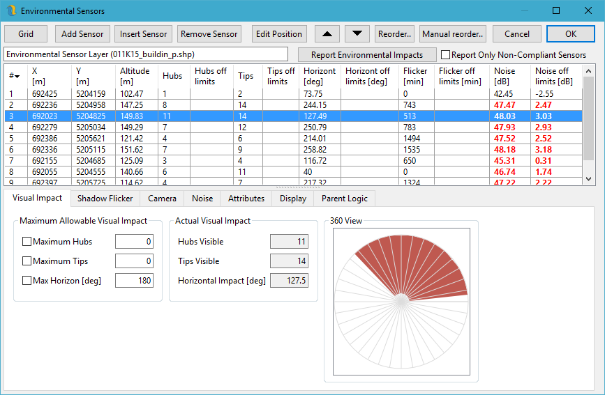
Figure 4: Environmental Sensor Layer Properties: Visual Impact Tab
Figure 5 shows the Noise tab, which reports the noise at the currently selected location and allows the user to set a noise limit at this location as well as to set a different receptor height. The noise value is calculated using the current noise model options. The octave band sound pressure levels only show when the octave band spreading model is selected in the Noise Model settings.
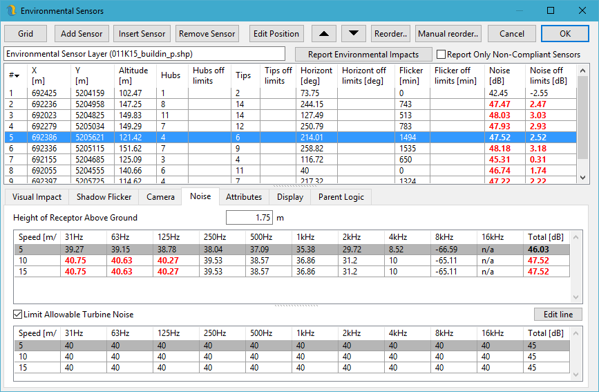
Figure 5: Environmental Sensor Layer Properties: Noise Tab
The limits on noise and visual impact are applied as constraints to the layout optimiser. In order to successfully place a turbine, the layout as a whole must not break the limits set in the environmental sensor layers.
It is theoretically possible to set limits on the shadow flicker that may be suffered at the sensor locations. However, due to processing requirements, it is not practical in Openwind as of yet. It is part of the framework, though, and could be included at a future date.
When setting environmental sensor limits on noise and visual impact, it is important to bear in mind that this may restrict a site to the point at which it is no longer possible to fit as many turbines into the site as the user would like. The optimiser may not be able to find a solution in such a case. If this happens, the user can remove several turbines—in the extreme case, this would leave just one turbine—and grow the layout (see optimiser options for more info) to discern how many turbines may be accommodated within the site while still satisfying the environmental impact constraints.
Shadow flicker is modelled using freely available NREL solar declination code SPA to calculate the sun vector minute-by-minute over the course of a year. Users may view the resulting information as a total number of minutes or in calendar form as seen in figure 6 (see Shadow Flicker ). It is important to check the button Use sensor bearing (from Camera tab) if you want this sensor to be directional with respect to shadow flicker.
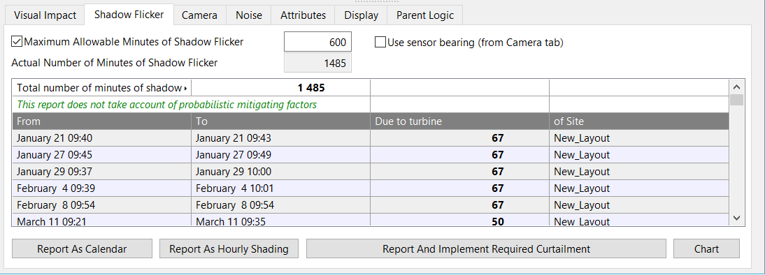
Figure 6: Environmental Sensor Layer Properties: Shadow Flicker Tab
- Report As Calendar - pops up a report which can be saved as text, XML, JSON or XLSX and includes a summary of the shadow flicker impact at each sensor along with a calendar of when, each day, shadow flicker can be expected and which turbine is the likely culprit. This essentially the same as is displayed in the bottom pane in figure 6.
- Report As Hourly Shading - gives the user the chance to save a text file containing the hourly shading at each sensor location. This is primarily for use in solar PV yield estimation modelling.
- Report And Implement Required Curtailment - This function treats the shadow-flicker limit at each sensor as a budget which gets renewed on January 1st at midnight each year. Once the budget is used up, no more shadow-flicker is allowed and the offending turbines should be shutdown during periods when they can or will cause shadow-flicker, depending on the settings chosen in the dialog in figure 8. See Figure 8 for the dialog and explanation.
- Chart - pops up a chart of shadow flicker at the current receptor for all days and times with days of the year along the x-axis and minutes of the day on the y-axis. Times before sunrise and after sunset are shaded yellow. Times with shadow-flicker are coloured the same colour as the site layer whose turbine is causing the shadow-flicker. See figure 7.
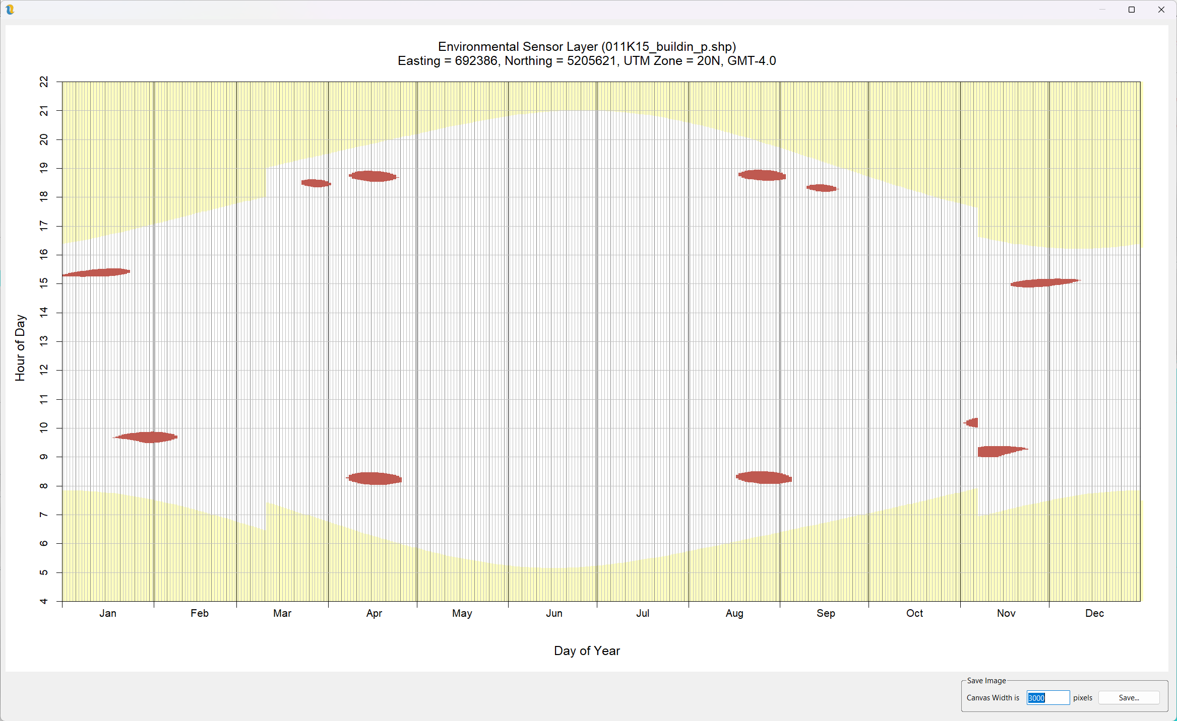
Figure 7: Shadow-Flicker Chart
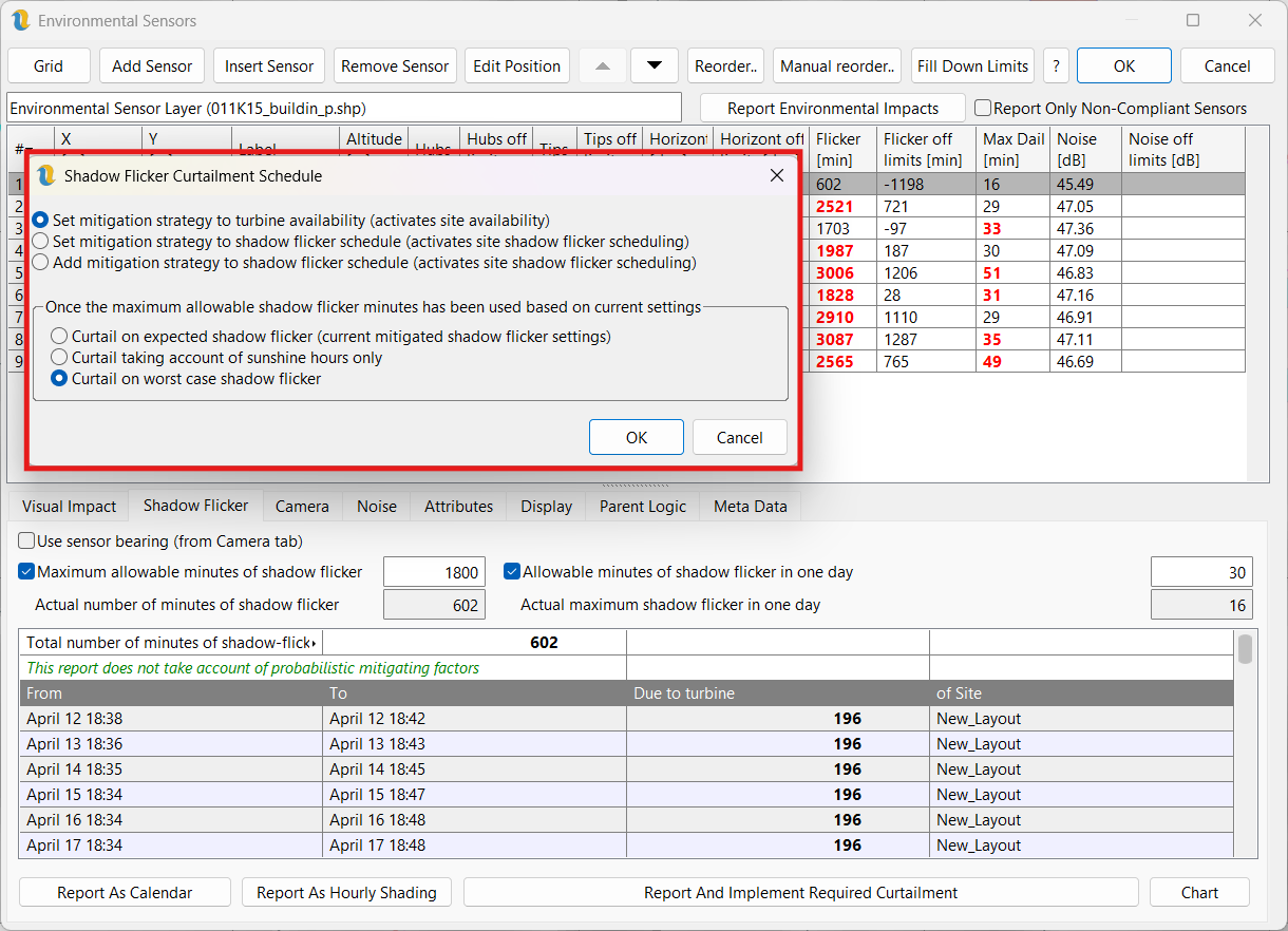
Figure 8: Implement Shadow-Flicker Curtailment
This dialog allows the user to specify how the curtailment should be calculated as well as how it should be implemented (availability time-series or scheduling interface). The budget is used up using the current shadow-flicker settings which should generally be setup to take account of time-series mitigation due to sunshine hours and wind regime (plus any existing schedules or time-series availability).
- Set mitigation strategy to turbine availability (activates site availability) - this is the most versatile option as it gets implemented as a time-series availability per turbine in the Availability tab of the site layer properties. This option can be used with any option below.
- Set mitigation strategy to shadow flicker schedule (activates site shadow flicker scheduling) - this option creates shadow-flicker avoidance schedules which shut off the offending turbine for any time that there could conceivably be shadow-flicker caused by that turbine, once the budget has been used up.
- Add mitigation strategy to shadow flicker schedule (activates site shadow flicker scheduling) - this is similar to the option above but it adds to the existing schedules instead of replacing them.
- Curtail on expected shadow flicker (current mitigated shadow flicker settings) - only available the the first option above. This option continues to use the current shadow-flicker settings (with any selected time-series mitigation) to curtail the offending turbines during periods when they would be causing shadow-flicker at any sensors whose budgets have been used up. This strategy assumes that each dwelling has some sort of sensor which can detect shadow-flicker and trigger the offending turbine to shut down.
- Curtail taking account of sunshine hours only - this option is similar to the one above except it only requires that direct sunshine can be detected during periods of worst-case shadow-flicker in order to shut down the offending turbine.
- Curtail on worst case shadow flicker - this is the most conservative option in that once the budget has been used up, Turbines are shut down during periods of worst-case shadow-flicker regardless of direct sunshine or wind direction. This is the safest and simplest but will lead to the largest losses.
The Camera tab, shown in figure 9, allows the user to output a KML file showing one or more wind farms from the currently selected point of view.
For a terrain profile between a turbine and a sensor, please see the section on Terrain Transect.
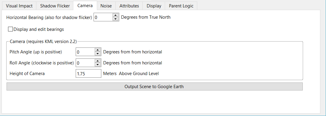
Figure 9: Environmental Sensor Layer Properties: Camera Tab
Display and edit bearings - this displays and edits the bearing of the view of each sensor. Changing the values of the bearing will be reflected in the map view in real time. Checking this box will make visible the bearings of all the sensors in this layer.
It is possible to edit multiple environmental sensor points at once by pressing the drag-box button on the toolbar and holding the left mouse button whilst dragging a box from top left to bottom right to enclose the desired turbines of the currently selected environmental sensor layer.
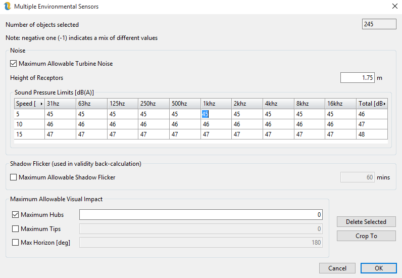
Figure 10: Environmental Sensor Layer Multi-Select Dialog
For values that are marked as “mix”, leaving these will leave different values in different objects. Otherwise, editing them and pressing OK will write the values in this dialog to all the objects that were selected.