Energy-Capture
The theory and validation work can be found in the document “Openwind Theory and Validation,” which is available online.
In short, Openwind contains a standard energy capture routine which, by default, sums the energy produced by the turbines over 72 directions and 71 wind speeds (0 m/s to 70m/s in 1m/s steps). For each direction and wind speed, it calculates the air density at each turbine, and the probability of the wind coming from that direction at that wind speed for each turbine. It also calculates the wake losses due to other turbines and modifies the wind speed at each turbine before entering that wind speed into the power curve.
Openwind contains a number of basic and deep array wake models. In addition, the user can run the energy capture with no wake effects. The basic wake models are covered in Basic Wake Models. The Deep Array Wake Models (DAWM) are only available in the Enterprise version of Openwind and are essential for estimating wake losses for utility-scale wind farms. Deep Array Wake Models are covered in Section 34.
The parameters for each wake model can be accessed individually from the Settings menu.
The Energy Capture settings can be accessed by going to the Settings menu and selecting Energy Capture. Figure 1 shows the energy capture settings dialog.
There are two sets of energy capture settings. The top set is used during layout optimisation. An optimisation runs thousands of energy capture calculations, and Openwind provides the option of running an abbreviated energy capture that only covers the wind speeds over which the turbine is producing significant power. The bottom set is used when calculating a full energy capture (also known as “Testing”). For the full energy capture, it is important to calculate across the entire range of wind speeds.
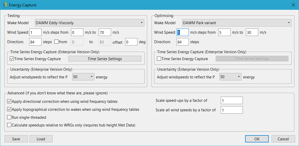
Figure 1: Energy Capture Settings
It is recommended that the number of sectors of the energy capture is an odd multiple of the number of sectors of the WRG (and the TAB file, if used). Whilst the code is written to allow overlaps, we have found in some cases it can cause unpredictable results. Generally, we recommend that calculation steps should be at most around 4-5 degrees wide in order to obtain a good precision in the wake model. Smaller sectors are not considered to increase the accuracy of the calculations but can be useful when considering wind sector management perhaps. In short, the safest bet when using a 12 sector WRG is to use a 12 sector met mast frequency table with 84 (12x7), 108 (12x9) or 180 (12x15) direction steps. Similarly, when using a 16 sector WRG you would be safest to use 80 (16x5) or some other odd multiple of sectors. For a 36 sector WRG, use a 36 sector wind frequency table with a minimum of 108 (36x3) or 180 (16x5) direction steps. Fortunately, in cases where we do need to use 360 direction steps, the amount of the energy capture calculation that is subject to overlaps diminishes.
When associating a TAB file, the energy capture uses the probabilistic distribution defined in the frequency table for every turbine associated with that mast. the WRG or WindMap object is used merely to scale the wind speed that is input to the power curve.
With the “Apply directional correction when using frequency table” option checked, the directional distribution at the mast is modified so that the overall probability of a sector is scaled by the ratio of the likelihood of that sector in the WRG at the turbine over the likelihood of that sector in the WRG at the mast. This permits considering the wind rose of the Adjusted WRG one instead of using the one of the associated mast. In figure 2 it is shown the sectorial directional frequency, mean wind speed and wind speed distribution considered at a certain turbine location by applying or not the “Apply directional correction when using frequency table” option.
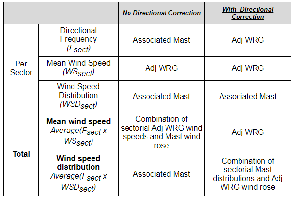
Figure 2: Effects of Applying or Not the Directional Correction
Applying or not this option will lead to different total mean wind speeds and speed distributions:
No Dir Correction: The total mean wind speed will usually not match the one of the WRG as it results from a combination of sectorial WRG wind speeds and Mast wind rose
With Dir Correction: The total wind speed distribution may not match the one of the mast as it results from a combination of sectorial mast distribution and WRG wind rose. This is the preferred option as otherwise, the speedup-up ratios between the met mast location and the turbine locations, combined with the difference in directional distribution, will result in mean wind speeds diverging further and further from the WRG wind speeds while at the same time diverging from the met mast wind speed distribution. The only time this wont be the case is when there is very little change in wind direction over the site due to the site being very simple or the wind-flow model being very simple.
The direction correction uses only the differences within the WRG in order to calculate a relative change in direction between the met mast and the turbine location. These correction factors are then applied to the directional probabilities within the met mast wind frequency table.
The option to be able to “Scale speed-ups” is really more of a research tool. Leaving it as one is the default. Giving it a value above one would exaggerate the influence of the wind-flow model whereas setting it to zero would eliminate the influence of the wind-flow model.
The option to “scale all wind speeds” can be used to carry out a more in-depth sensitivity test by re-running an in-depth energy capture with everything the same except wind speeds scaled up or down (and the corresponding decrease or increase in ambient TI).
The option to “Apply topographical correction to wakes when using frequency tables” is used to apply speed-ups to the value of the thrust coefficient used to calculate the wake from a turbine. Its goal is to take terrain into account while calculating wakes. This is an attempt to compensate for the way in which wake models are run which is to say, one direction and one wind speed at a time.
The option to “Calculate speedups relative to WRGs only” treats speedups in a similar way to the direction correction in that it is based on the relative changes within the WRG. This can be used, and is recommended, whenever there is hub height met data, which is almost always as the met data tends to be sheared up to every hub height of interest before being imported into Openwind. This option can be used with adjusted WRGs in which the WRG closely matches the met mast. It can also be used in cases where the WRG does not match the met mast statistics. This is because it applies the relative changes in the WRG and does not reference the met mast beyond its location. This can be useful in cases where the user is confident of the shape of the WRG and does not want to adjust to a new set of met data but merely wants to use the WRG to extrapolate from the met data out across the site. We recommend always using this option.
Uncertainty is covered in Uncertainty. Time series energy capture is covered in Time Series Energy Capture.