Offshore
Offshore LCOE
General Settings
When applying LCOE optimisation to offshore projects, the first thing to do is to disable the access roads here
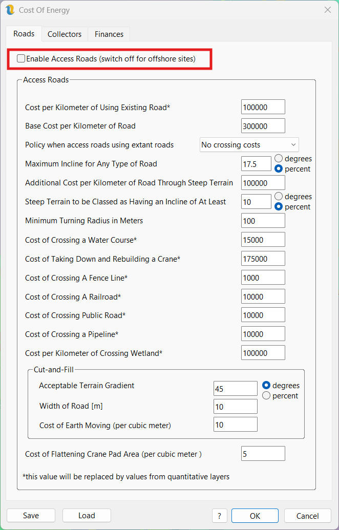
Figure 1: Cost Of Energy Settings - disabling access roads
The next thing you might want to do is to use Sharma for determining collector system circuits
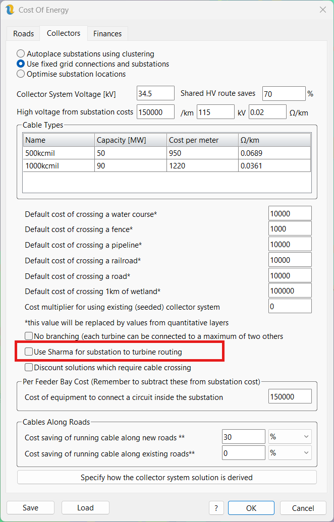
Figure 2: Cost Of Energy Settings - setting Sharma to avoid cable crossing
Sharma selects circuits based on a star topology and is less optimal than Esau-Williams (the default algorithm in Openwind) but is less likely to lead to cable crossing which can be very expensive when building offshore wind projects.
Turbine Foundations
You can specify multiple different turbine foundations for any given turbine type by going to the Costs & Offshore tab of the turbine types dialog.
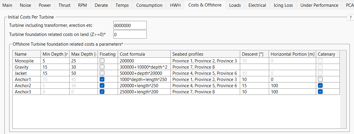
Figure 3: Turbine type offshore foundations and mooring types
For turbines with a negative bathymetry value (some bathymetry layers reserve positive values for terrain and so Openwind only recognises negative values as water depth and will attempt to convert on input bathymetry files which do not use this convention), they are considered offshore. For offshore turbines, the grid of offshore turbine foundations is used and the value in the “Turbine foundation related costs on land” box is ignored.
The grid accommodates both fixed and floating foundation types with the “mooring” checkbox determining which are which. In figure 3 above, the first three lines describe fixed foundations, their minimum and maximum water depths and the range of applicable seabed soil provinces in which they can be used. Each foundation type can have a fixed and/or variable cost component. Water depth can be a driver of fixed foundation cost and can be input as either “depth” or “z”. If the soil province is left blank, that foundation or mooring anchor type can be used in any/all soil provinces.
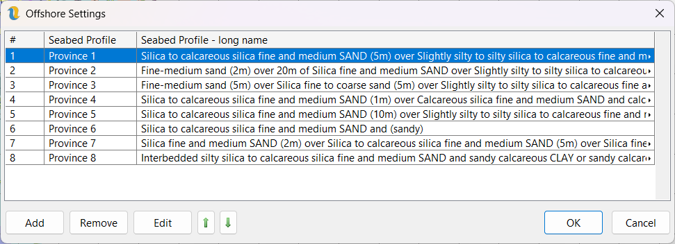
Figure 4: Offshore Settings - definition of qualitative seabed subsurface categories
Floating offshore turbines are covered here