Floating
Offshore Floating
The settings for offshore fixed turbine foundations and soil province definitions are covered here
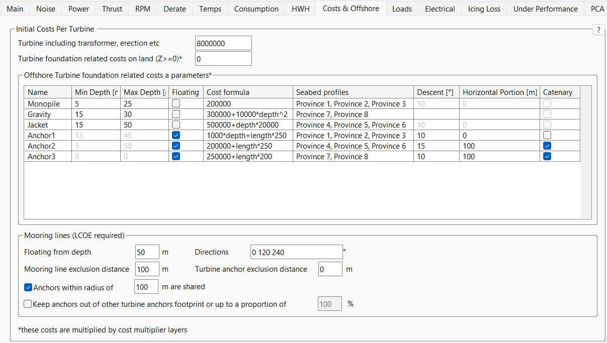
Figure 1: Offshore fixed and floating foundation options
Mooring-anchor pairs are considered as a single item in Openwind and so a single item in the grid above describes both anchor and mooring line and the cost formula needs to cover both with the fixed portion being largely composed of the anchor and any horizontal fixed length portion and the mooring being costed as proportional to its length. In the example for “Anchor2” given in Figure 1 above, the “length” variable is the length of the catenary mooring line in meters and is multiplied by 250. The length of the catenary mooring line is determined by the initial descent angle at the turbine and the water depth where it touches down on the seabed, with the assumption that the gradient of the catenary curve reaches zero at the seabed. For non-catenary, a straight line is used with the descent angle all the way to the seabed, thus representing a taut mooring line.
In the box below the foundation and mooring system grid, the variables take the following meanings:
- Floating from depth - There is no depth constraint for individual offshore mooring systems and only this single minimum depth is used to determine whether a turbine is floating or not.
- Directions - a list of space separated angles in degrees. There can be any number of mooring lines (usually between 3 and 6). Mooring line angles are fixed for all turbines of this type. However, a site layer specific offset can be added in the site layer properties.
- Mooring line distance - this is the 2D minimum distance required between mooring lines.
- Turbine anchor distance - this is the minimum 2D distance between a turbine and any other turbine’s mooring system.
- Anchors within radius of [X]m are shared - This is the proximity within which the anchor can be shared. This assumes a pile anchor with no horizontal portion. The fixed and “depth” or “z” related portion of the cost formula is shared with the “length” or “x” related portion not being shared. The rationale behind this is that the mooring line is not shared and is proportional to the length variable. It is assumed that there is little or no horizontal portion for shared anchors and that shared anchors are fixed to the seabed rather than being drag anchors or similar.
- Keep anchors out of other turbine anchor footprints or up to a proportion of [X]% - this is the option to keep anchors out of the footprint of a neighbouring turbine and its anchors. The footprint is defined here as the polygon formed by the linking each anchor to its neighbour. This can be switched on or off and it can also be scaled by a percentage with that scaling being the fraction of the distance between the central turbine and its anchors.
The constraints above can be combined to create a variety of shapes. However, it is recommended that you use the minimum set of constraints that achieve your goal.
All this floating functionality can only be used in conjunction with the LCOE optimiser